
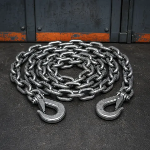
Lashing Chains
Transport chains for construction materials, precast elements and project cargo, subject to model confirmation.
View Lashing ChainsSecure precast elements, construction materials, site machinery and oversized project cargo with a practical chain lashing plan.
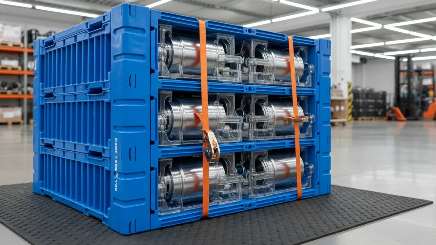
Construction loads often combine fragile edges, irregular geometry, heavy mass and changing site conditions. Restraint must remain practical from yard to job site.
Precast elements, forms and site equipment rarely present a simple rectangular loading footprint.
Concrete edges, finished faces, coated steel and architectural surfaces can be damaged by concentrated contact or movement.
Rough access roads, temporary yards and multi-stop delivery can create different movement and handling conditions.
Oversized cargo can block trailer, frame or deck anchor points, making the connection sequence important.
The points used to lift a component may not be suitable as the sole points for road restraint.
Loads may be partially unloaded at several sites, requiring clear identification and a controlled release sequence.
Select the restraint method after reviewing the element shape, support points, vehicle, site handling and delivery sequence.
| Application Scenario | Recommended Product System | What It Solves | Project Focus |
|---|---|---|---|
| Precast beams and panels | Lashing Chains + Compatible Binders + Edge Protection | Controls movement while protecting edges and finished surfaces. | Review supports, lifting vs tie-down points, panel orientation and delivery access. |
| Concrete pipes and manholes | Lashing Chains + Hooks + Project Accessories | Addresses rolling, sliding and irregular support conditions. | Review chocks, cradles, contact areas, anchor spacing and release sequence. |
| Formwork and temporary structures | Chain Assemblies + Load Binders | Repeatable restraint for reusable forms, frames and site equipment. | Review frame geometry, protrusions, surface finish and return handling. |
| Site machinery | G70/G80 Lashing Chains + Load Binders | Direct restraint for compactors, generators, lifts and other mobile plant. | Confirm machine connection points, center of gravity, deck contact and route. |
| Rebar and steel bundles | Lashing Chains + Hooks + Edge Protection | Controls long bundled material during road and project transport. | Review bundle stability, sharp edges, dunnage and vehicle anchor points. |
| Multi-stop project delivery | Matched Assemblies + Accessories + Documentation | Makes staged unloading and repeated site handling easier to control. | Define load identification, release order, inspection points and remaining-load stability. |
Combine the primary chain restraint with compatible binders, hooks and accessories that suit the cargo, vehicle and job-site sequence.
Transport chains for construction materials, precast elements and project cargo, subject to model confirmation.
View Lashing Chains
Finished assemblies for repeatable loading and recurring project delivery.
View Lashing Chain Assemblies
Ratchet and lever binders for controlled tensioning and release on compatible chain systems.
View Load Binders
Hook styles for trailer, deck, frame and cargo connection arrangements.
View Lashing Hooks
Links, shackles and fittings for adapting the restraint path to non-standard project loads.
View Chain Accessories
Webbing options for protected packaged materials or supplementary restraint where appropriate.
View Ratchet Straps & Webbing
When the cargo, trailer, deck or handling process falls outside a standard setup, LashLok can coordinate a project-specific configuration.
Request Project SupportThese references describe planning approaches. Every construction load still needs a cargo-specific review before transport.
Large panels needed stable support and protected contact points during yard-to-site delivery.
Review support spacing, panel orientation, lifting and tie-down points, edge protection and the unloading sequence.
Cylindrical concrete elements required control of rolling and lateral movement on a project trailer.
Coordinate cradles or chocks with the chain path, hook access and staged release at the receiving site.
Multiple pieces of site equipment traveled together with different centers of gravity and connection points.
Create separate restraint paths for each unit and keep the inspection and unloading order clear.
Reusable frames and forms were moved through several sites and needed a repeatable return transport setup.
Standardize the chain assemblies, contact protection, load identification and release sequence by frame family.
Precast and construction cargo should sit on stable supports before the chain path is finalized.
Review where the element can safely rest, where it can move and where supports must be protected.
Separate sliding, tipping, rolling and impact risks in the loading plan.
Make sure connections can be inspected and released at the job site.
Construction logistics often involve temporary yards, site access constraints and partial unloading.

List the loading yard, carrier, site, crane or forklift and receiving sequence.
Confirm that the load remains stable after partial unloading or repositioning.
Mark hardware sets and load elements so site teams can follow the planned release order.
Concrete, coated steel and architectural finishes can be affected by pressure, abrasion or direct chain contact.
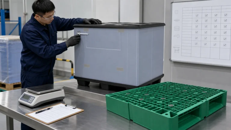
Review corners, faces, coatings and contact areas before loading.
Check for chain pinch points, concentrated pressure and interference with supports.
Use photos and notes when the cargo will be handled by several teams.
A standard method helps carriers and site teams control staged unloading and return transport.

Document what is unloaded first and how the remaining cargo stays restrained.
Keep chain, binder, hook and accessory combinations compatible and identifiable.
Reconfirm the plan when the trailer, route, load order or job site changes.
We connect the cargo geometry, support arrangement and delivery sequence into a practical project brief.
We review element dimensions, weight, shape, surface condition, lifting method, job-site access and delivery sequence.
We confirm trailer or deck layout, supports, dunnage, anchor points, clearances and the expected loading environment.
We match chain grade, finished length, hook style, binder type, accessories and contact protection to the load.
We document loading order, inspection access, partial unloading, remaining-load stability and release sequence.
Where required, we coordinate drawings, product details, samples or project-specific specification confirmation.
We support inspection records, loading photos, packing information and project logistics coordination according to scope.
Working load limit must be confirmed for the selected model, configuration, angle, anchor point and application.
Dunnage, cradles, chocks, edge protection and contact surfaces should be reviewed with the restraint path.
Lifting points and tie-down points should be confirmed separately for each precast or project element.
Loading photos, site notes, inspection records and shipment documents can be organized for qualifying projects.
Specification sheets, dimensions and model-level information may be provided according to the selected product and project.
Final construction cargo restraint must be confirmed by the responsible transport and site teams for the actual load, vehicle, route and handling sequence.
We can review precast dimensions, weight, support points, lifting and tie-down points, surface condition, trailer layout and delivery sequence before recommending a compatible restraint approach.
Not necessarily. Lifting and transport restraint serve different purposes, so each point should be confirmed for the intended load case by the responsible project team.
Yes. The review should include rolling risk, cradles or chocks, contact protection, anchor spacing, chain angle and the unloading sequence.
Yes. We can help structure the hardware list, load identification, inspection points and release sequence for staged unloading, subject to the project details.
We can coordinate compatible chains, finished assemblies, binders, hooks and accessories as a project set after the loading configuration is reviewed.
Please provide drawings or photos, dimensions, weight, center of gravity where available, supports, vehicle or deck information, route, site sequence and quantity.